
Impedance-driven NMEA 2000, & SimNet gets a “Noise Filter”
Maretron’s Rich Gauer has repeatedly tried to explain to me how NMEA 2000 is an impedance-driven networking technique and that’s why it’s so important that the cabling have the right electrical characteristics with the proper termination. He can get quite passionate about the subject, almost poetically describing clean waves of N2K data bits getting distorted by reflections to the point that microprocessors along the backbone can’t recognize them anymore. But then again Rich is an electrical engineer and Maretron may well have more troubleshooting experience than any other company with the large N2K networks where impedance problems tend to show up. Installs or other manufacturer’s gear that cause trouble because the impedance rules aren’t abided to get him upset! However, a guy like me is way better at visualizing the dynamics of a hull passing through ocean waves, and I couldn’t begin to fathom the “Transmission Lines, Reflections, and Termination” PDF Rich once linked me to. Which is why I am especially taken with the graphic N2K analysis (above) that our friend Kees Verruijt posted on his Yacht Electronics blog…
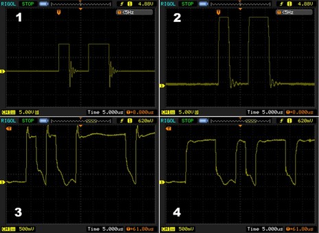
Kees has equipped himself with a Rigol DS1052E digital oscilloscope and he’s been using it to peep into his SimNet network. What we’re seeing on his screens really are data bits, though he tells me they’re more accurately defined as NRZ or Non Return to Zero encoding. If you read Kee’s entry you’ll see that screen #1 shows a very short, simple network with no terminating resistors — which at least partially accounts for the ringing that follows the nice square NRZ waves, as demonstrated in screen #2, in which the same backbone has some terminator-style resistance added. Screen #3 shows what’s actually happening on Kee’s own boat with 13 active sensors and about 60 meters of SimNet cabling. Apparently it works, but those waves are looking a little raggedy. Or were until he installed a SimNet Noise Filter as seen in screen #4.
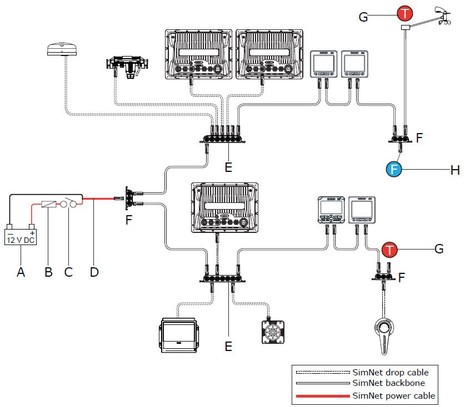
SimNet Noise Filter? Nope, I hadn’t heard of that component either, and can’t find any mention it on Simrad’s SimNet page or in the SimNet manual. But as Kees wrote about in an earlier entry, the latest NSE manual suggests that the Filter be used on large SimNet systems or when there’s a long mast cable as illustrated by the “F” in the diagram below. He’s also heard that the SimNet cable wires I once documented have been upgraded, but I don’t know that for sure. Apparently after all these years — and, mind you, SimNet was one of the first NMEA 2000 cable and connector systems available — there have been some impedance issues.
This is interesting, but let’s not make too big a deal about it. I’ve had zero problems with the SimNet system I installed on Gizmo last summer, and I appreciated how thin the cables are and how loose Simrad is about design. (Note the daisy-chained backbone in the diagram, for instance, which may cause smoke to come out the ears of NMEA’s Technical Director 😉 Even Rich Gauer — after warning about the dangers of non-spec cables and installs — adds that “This isn’t to say that a small network can’t get away with breaking the rules because the network is small enough where impedance mismatches don’t really cause a problem.” Which I’ve proved to myself many times in many ways! In fact I’m right now installing yet another ‘temporary’ N2K network in Gizmo as I need to go cruising tomorrow, and included is all sorts of older Airmar and Garmin cables that don’t meet the OVDA DeviceNet specs that NMEA used for the physical layer of N2K…but I’ll bet it will work fine. On the other hand, I’m also finishing up design details for Gizmo’s permanent N2K backbone and I’m going to spend a little extra money to make sure that it’s a good impedance environment so I don’t run into trouble as the number of devices and volume of data inevitably grow.


The way I was taught (back shortly after the other Ben flew his kite), in a DC system impedance and resistance are equivalent because there is no phase angle.
So, I begin to wonder about the impact of connector and conductor corrosion and engine room heating on a system that is impedance dependent. If this data is from a clean network in a dry lab environment, the waves will look even uglier out there in the great wet, especially after time gets its teeth into metal parts.
The leading spikes don’t bother so much because their sign is unambiguous. What does bother is the ugly stuff at the bottom where sign becomes variable. Waveforms like this need a fair amount of post processing to insure one doesn’t get a flipped or a skipped bit. Given the excellent state of current microprocessors, most of the sensors and receivers should be pretty error tolerant, we aren’t talking ICBM guidance. But noise in a system never gets less (until it hard fails).
I guess what I would wonder as I contemplate an N2K redo on my boat is whether 85 feet, the longest cable run, represents a small, mismatch tolerant network.
Impedance issues are often on that list of things you don’t worry about and don’t bother to check, until they cause trouble. By then it’s a real headache to track down the troublesome component.
In the undergrad nuclear labs where I often serve as TA, we usually teach the students to start with the sensor, and add only one device at a time- looking at the signal at each step to ensure it makes sense and is being processed correctly. Otherwise, a 50 ohm cable will get connected to a 93 ohm input, and the ringing will make a counter or rate-meter go haywire, or overwhelm an MCA’s triggers. You have to use the right parts, and check what you’re getting at each stage.
Properly installed N2K should be pretty tolerant of this sort of noise- its signal levels are pretty unambiguous, especially when compared to something like DOCSIS that’s full of high-k QAM and other nasty encodings. But there are all sorts of ways to distort the N2K signal (bad plugs, daisy-chaining, etc.) and, if Simrad thinks a filter might be handy on a long, complex run, I certainly don’t see the harm in adding one (apart from the cost).
Matt,
You bring back memories, I had similar experiences working at a Cyclotron Institute in the SW. Ringing issues drove us nuts.
NMEA2000 and CAN bus are very robust and tolerant by design (dare I say foolproof :-). In contrast, look at real world USB 3.0 signals sometime; They’re pushing the envelop so far that it’s a wonder it works at all.
Very much agree, Mic. And the DeviceNet cable and connector standard is also robust and well proven, plus NMEA applied extra cautious limitations to its use. Some other DeviceNet applications, for instance, seem to permit daisy chaining.
And no worries, Christopher, the conservative NMEA limitation on a Micro size backbone cable system is 100 meters, with the total drop cable lengths not to exceed 78 meters and no single drop cable (or combination of multi-port and cables) to exceed 6 meters. That gets you a maximum of 50 devices.
This evening I fired up both SimNet and N2K networks on Gizmo with nary a problem…and they are a bit funky.
Hi,
Interesting data. I have a question/comment about the scope plots:
The Canbus spec has a “low” voltage level of 0V to +1.5V, and a “high” level of +4.0v to +5.5V. As a couple of people state above, this makes signal interpretation quite unambiguous and tolerant of a high level of noise.
I’ve tried to reconcile those trigger levels with Kees’ scope plots, and can’t figure it out. It looks to me that plot 1 & 2 are on 5V per division, and 3 & 4 are on 500mV per division, but if that’s true, none of the signal levels make sense within the Canbus specs.
Ben, or Kees, can either of you comment on that? Am I interpreting the vertical scale incorrectly?
BTW, the Rigol scopes look to be quite good value for money. Kees, would you recommend it? Is it missing any capabilities that you wish it had?
Thanks,
Paul.
Hi Taniwha,
RE Rigol scopes. I worked as a App Engr for Agilent/HP until 2009. I focused on scopes and their applications. I have compared some of the Rigol scopes. They do represent a good value. BTW, The Agilent 1000 series are rebranded Rigol scopes.
Paul,
Plots 1 & 2 were made with the probe in 1:10 mode, months before the plots 3 & 4.
As to the voltage levels, sources apparently differ. According to http://www.interfacebus.com/CAN-Bus-Description-Vendors-Canbus-Protocol.html it is: High; 2.75v to 4.5 volts, Low; 0.5 to 2.25 volts, Differential 1.5v to 3.0 volts.
I quite like the Rigol scope, but have to admit I have no recent experience with any other modern scopes. My previous one is a 25 year old Hameg 20 MHz scope. It seems to be pretty quick (GHz sampling rate) for the money. In hindsight maybe I should have gotten a USB style scope, which would making screendumps even easier (now I have to dump them to a USB stick in the Rigol, and then transfer those to my Mac.) On the other hand, making measurements in the field is a lot easier with a complete scope. All in all I am very satisfied with the Rigol. Compared to my old analogue scope that I used to debug 6502/Z80 generation home built computers, this is MUCH easier. You can have it trigger on a signal level, stop automatically and then scroll back to where the interesting bits are. Amazing, no need to get the computer to go into a reliable loop!!
Thanks Kees. I might get one of those since they seem to be great value for money.
Actually my bus level comment came from exactly the same page as you’ve referenced. If you scroll down from where you got your voltages, about a page lower you will see a table called “CAN Bus I/O Characteristics”. As you can see in that the “Output Voltage” is listed for both High & Low states, and that’s what I was referring to.
Do you, or anyone else, have any idea what the difference is between what you referenced and what I did?
Thanks,
Paul.
Id I recall correctly, CANbus allows the lines to float when no nodes are dominant. In this recessive state, the differential signal lines are separated by no more than 0.5 V. The actual voltage doesn’t matter but is somewhere between low and high (typ. 2.5 V or so).
A dominant state (i.e. a signal) is created by one of the nodes applying a low voltage to CAN_L and a high voltage to CAN_H. Nodes recognize a dominant state when the differential lines are separated by more than 0.9 V.
Exactly what voltages are applied to CAN_L and CAN_H shouldn’t matter too much- in the dominant state, there’s a voltage difference. In the recessive state, the termination resistor allows the two to equalize. As I understand it, nodes are only supposed to care about whether or not there’s a difference between the lines- provided they’re within reasonable voltages (0 to ~1.5 V and ~3.5 to 5 V).
It’s been a while, though, so don’t quote me on this…
I’m no expert either, but I think you’re right, Matt.
To add on to that, the way that I read the publicly available documentation on CAN the way it does collision avoidance without throughput degradation is that a 1 is ‘dominant’ and a 0 bit is recessive.
This works like this: All devices monitor their own transmissions. When a sender detects that it that has sent a zero (recessive) but sees a one (dominant) on the bus it knows that someone else is also sending data. It stops immediately, at that particular bit. Thus the other sender is guaranteed to complete its message.
This does mean there is a hierarchy in who gets more priority. Obviously the priority of a message comes first, so that a high priority message always indeed gets priority.
For this all to work the network must be such that:
(a) a zero bit is “sent” by not driving the bus.
(b) a one bit is sent by making the bus active.
(c) all senders will see each other within a (fraction of) the bit transmission time. This limits the max. length of the bus.
Note that (a) implies that the termination and general line characteristics of the bus are such that the data lines float back to the recessive state in a timely manner. In other words: no (proper) termination == problems.
What is inside the SimNet filter – is it passive (non-powered) or active?
I’ve been told it contains a 120 Ohm termination resistor as well as a 220 μF capacitor. So it is completely passive. It lowers total impedance to 120/3 = 40 Ohm instead of the standard 120/2 = 60 Ohm.
Apparently it was cooked up by Simrad when Hanse started equipping 1000’s of sailing yachts with large(r) N2K networks, with the network cable going all the way up into the mast.
Kees, Ben, et al, thanks for making a very complex subject basically understandable to me, and it was very informative. This is not my professional milieu, but I was able to follow the discussion.
Kees, Matt,
Thanks for the clarification: it makes the spec.s on that web link make more sense. There’s therefore no conflict between what Kees quoted and what I did.
The only price I can find for the Simrad filter is US$25, which makes it an expensive box, connector, resistor, capacitor.
I have the Airmar PB200 at the top of my mast, and it seems that they’re suggesting putting the filter at the bottom of the mast if you run the backbone to the top (which you have to since a mast is taller than the max N2K drop line allowed).
I cut the bottom connector off the cable to run it, and reconnected it through a simple screw connector strip, with seemingly no adverse effects, so I guess I could just add components to that.
Anyone have any reasons why that wouldn’t work as well?
At risk of being grumpy again and jumping in, I am continually amazed at why this outdated technology was adopted for NMEA 2000. It has termination problems, resistive and inductive issues and of course the indefineable impedance problems. As most Engineers on here know, impedance is a difficult thing to quantify and measure, without horrendously expensive test equimpent. For most of us it can really only be calculated vectorially using the standard formula.
I inherired one of these sort of networks at a large School I worked at over 30 years ago nearly. We were using Win 3.1 then which had just come in. To say it was problematic would be an understatement, It soon got replaced with an Acorn network, and then later in 1998 with a (mostly) fibre to desktop ethernet 10/100 system which was upgraded last year to Gigabit.
I can see why NMEA did it, hoping that it would be more immune to interference being screened, and of course they would have probably liked to have gone fibre, but the bend radius prevents this on most vessel installations.
Personally If I had been given a blank sheet to define N2000, there are better ways of achieving a managed quick multidrop system around. The security industry has several models which network manage security and fire systems FI, which either use Parallel or HSS Double Screened systems, which have to be stand alone sytems ie not using an ethernet system, for some regulatory issues with hotels etc.
Off topic I know, but I just thought I’d add my shot
in.
Steve
I’d use a much stronger word than ‘grumpy’, Steve! I’m not even sure you actually read the entry before jumping in as save-the-day engineer. But, where to start?
First of all, DeviceNet — which is what we’re really talking about here, the physical layer standard that NMEA adopted for N2K — is certainly not an “outdated technology”. Except, it seems, to PC networking geeks who’ve never heard of it (not just you, Steve, I’ve been around this carousel before). Ditto for CanBus, which has become the standard for mission critical vehicular networking. And ditto for NMEA 2000, which is built on top of DeviceNet and CanBus and has become the standard sensor network on boats (that aren’t old).
And get this: SimNet cabling and connectors is not DeviceNet and is certainly not NMEA 2000, which put some limits on DeviceNet just to be super safe. For whatever reason, Simrad decided to design their own version of NMEA 2000 cabling, and it’s most certainly not NMEA 2000 certified, which you can verify at NMEA’s site. Nor, by the way, does it meet the impedance standards of DeviceNet (according to my sources).
But get this: Even though SimNet meets neither the DeviceNet nor N2K standard, it’s worked fine in many installations for many years. What’s discussed in this entry is apparently minor problems with especially large networks that can be solved with a $25 plug-in filter. And yet you’re willing to say that NMEA 2000 has “termination problems, resistive and inductive issues and of course the indefineable impedance problems.” WTF?
Sorry, Steve, but I get grumpy myself. It seems like I can not write about nuances in what is a wonderful marine sensor network standard without somebody claiming that the whole thing was a bad idea. Honestly, I don’t understand it. But I’d like to. I’d appreciate your answer to a simple question: Have you ever used — or, better still, installed and used — a NMEA 2000 network?
God knows Ben , I have my views on NMEA 2K. I agree and disagree with you . I have installed 2K systems. The experience varies from “easy” to deeply frustrating, you yourself have highlighted some of the problems, issues like sensor PGN incompatabilites, source selection problems, cabling non-standards.
Yes it works and its worlds better then NMEA0183, but it could be a lot better, especially if NMEA make it and open standard ( a cheap open standard). That way we would see more ancilliary equipment, especially badly needed diagnostics equipment. Its a very hairy network to diagnose at sea for example, as very few manufacturers build any serious diagnostics into their equipment.
Dave
Well said Ben.
Kees: As always, a great breakdown of a complicated subject.
Dave: I can be accused of bias, however I would be remiss if I didn’t mention that a good number of marine engineers trust the Actisense NGT-1 (operating with NMEA Reader) to be a very useful diagnostics tool for NMEA 2000 network issues.
Whilst it cannot show you the oscilloscope view of the bus, it can show you what PGNs on the bus are actually ‘receivable’ from each device and all the data values currently inside each one of those PGNs. It will also list all of the NMEA 2000 devices currently operating correctly on the network, and allow you to change instances and installation details in all those devices that support those features.
Steve: Would you classify the International Space Station (ISS) or the automotive industry as “outdated technology”? CANbus networks are used on-board the ISS because they are very robust at coping with the noisy environment of low-orbit. The majority automotive manufacturers similarly use it for its reliability.
This is only true if the correct cable quality and impedance is used to create the CANBus network, which is the subject of this thread.
As to onboard Ethernet, here are my statistics for the first 8 months of owning our new sailboat:
Wired Ethernet devices: 6
Time spent uploading new firmware to 1 device: 2 hours (didn’t want to play nice with DHCP server)
Time spent debugging physical HW: 4 hours (2 bad wire crimps caused flaky connections)
Wired N2K devices: 13
Time spent uploading new firmware to 7 devices: 2 hours
Time spent debugging physical HW: 1 hour (installing Simnet Noise Filter just to be on the sure side)
In other words, the N2K network has been utterly reliable. My research into the electrical behavior was done out of curiosity, not because my network was not working.
My Ethernet network has, so far, caused much more trouble even though it is 1/3rd the size and point-to-point making it — in theory — easier to debug.
On board ethernet has ranked least reliable for me as well.
Worst: Wired Ethernet devices: 5
5 year total time spent debugging network or wiring: approx 40 hours (at least 4 seperate problems)
Mystery Problems Still Unsolved: 1 (lost packets, sometimes two charplotters don’t see each other and complain)
Outages: 4 Partial outages (3 software, 1 failed connector)
Wired NMEA-0183 devices: 5
5 year total time spent debugging network or wiring: approx 20 hrs (my wiring error, somehow it still worked most of the time)
Outages: Twice, partial loss of functionality
Wired Seatalk devives: 11, now 10
5 year total time spent debugging network or wiring: approx 4 hours
Outages: 2 total outages (tridata device went bad, disrupted all devices; short of data to ground on yard installed connector)
Best: Wired N2K devices: 9
2 year total time spent debugging network or wiring: 30 minutes
Outages : 1 (my fault, undersized fuse)
Opps, I meant to write, 3 minutes, not 30 minutes under N2K.
Dan,
When an NMEA2000 Network with say 9 nodes or even 25 nodes does fail, how would you troubleshoot it?
Answers:
1. If there is a break in the power wires, you can unplug nodes from end to end and try to find the break.
2. If there is a break in the data wires, you would have to perform a similar manual trial and error excercise.
With a modern Ethernet network, you can simply find the hub or switch and look at the lights.
Your statistics are only one of millions of possible problems.
Sorry, “NMEA 2000 Critic”, but I don’t buy your “answers”. If there was a power or data break in, say, an N2K depth sensor, or its drop cable, it would be simply indicated because you’d stop seeing depth on your system. But I’ve never seen a failure like that, and I rather doubt that you have.
What’s neat about these recent comments from Kees and Dan is that they’re actually using Ethernet and NMEA 2000 on their boats, and thus they have a real sense of where they’ve had to spend time trouble shooting in the real world. What’s your real world experience of N2K, “NMEA2000 Critic”?
Dear Mr.NMEA 2000 Critic, “It’s not what’s for dinner, It’s what’s for dinner.” N2K is here to stay for a while at least, despite what ever flaws it might have. The emphasis should be on how to improve it, because for the time being we all have to live with it. I have, I suspect installed more N2K devices this year than the collective crowd has altogether. My only problems have been with manufacturers not keeping up to date with the the PGN’s, some minor errors made by myself, and my pet peeve, the inability of some manufacturers to stick to standard connectors forcing me to procure expensive proprietary adapters. Lets see now, a blue female connects to a red male, as if you can tell the sex half the time. I think some of these connectors are really transsexual hermaphrodites, at least looking at some of the catalogs. I have also stared at those happy blinking green lights at the Ethernet switch, and the $%^!! device still doesn’t work. You can’t make me go back to 0183. Signed, Grumpy in Sarasota
1. SimNet and SeaTalkNG are not N2K. Being electrically and (mostly) PGN compatible is not the same thing as following the standard. (For this reason, I have little interest in owning Simrad or Raymarine equipment- I don’t want to support companies that made a conscious decision to subvert a widely accepted standards process.)
2. N2K, the J1939 protocol on which it’s based, and the DeviceNet architecture and the underlying CANbus technology are very robust and well-proven in the field. There’s nothing wrong with a protocol being “old” if that also means it’s widely supported and all the lower-layer bugs have been worked out.
3. Ethernet is very reliable and easy to troubleshoot IF the OEMs follow the accepted specs and protocols. If they’re using Ethernet for the datalink through session layers, but undocumented proprietary stuff for physical and presentation/application layers, of course it’s going to be a bugger to troubleshoot. And if they followed the specs, you wouldn’t need to purchase an OEM’s $500 hub because the $60 one from a third-party isn’t “compatible”.
Today’s entry about testing the Garmin GDL 40 speaks a bit to NMEA 2000’s abilities. To have a cellular modem powered by and delivering what seems to be 3G data via N2K is pretty neat. The GDL seemed able to send quite a pile of weather data to an MFD in about 23 seconds without affecting higher priority data on the network (since all proprietary PGNs are low priority). I didn’t mention it in the entry but I installed the GDL “hot” — that is, with the network powered up — no problem.
http://goo.gl/em00Z