
Adventures in NMEA 2000 Wiring – Part I
Guest entry by Dan Corcoran —
Breeze Pleeze has received nearly half of her new NMEA 2000 backbone, actually two of them, and I thought I would describe the thinking behind my network design.
Two backbones, yes that’s right. The thought was to power a smaller network when my sailboat is on a mooring or at anchor. Most cockpit displays, most sensors (like the Airmar PB200), future autopilot, and so forth would be on a blue (blue water) network. While on the grey network would be things I would want active still at anchor such as a GPS (plot boat movement at anchor), fresh water tank sensors, battery monitor, and a chartplotter to display this information and weather (I currently have a pair of Raymarine e-series chartplotters and a Raymarine Sirus Weather Receiver). This will be an improvement over my current arrangement where I did not plan a power saving mode … and hence nearly all my marine electronics are powered up to keep an eye on how well my anchor is holding and the current weather picture at my finger tips.
For my blue and grey networks, I am using NMEA 2000 wiring components from Maretron including double end cord sets available in blue and grey, and chose the “Mid” size backbone for its larger diameter power wires that result in significantly reduced voltage drops vs. the more popular micro size. Ben wrote about this here. This is especially important to me as my golf cart style 6v batteries tolerate being discharged down to 20% every once in a while, effectively giving me a better power to weight ratio than standard lead/acid, but the voltage levels can get really low, such that I wouldn’t want them to drop yet another volt traversing my N2K backbone.
I actually considered the largest sized cabling offered by Maretron, but it appeared hopeless to get through my conduit. I suspect the same voltage drop concern I have for low tech golf cart batteries will be true for some high tech battery technologies that are coming down the road capable of being discharged to very low levels without reducing charging cycles. Another bonus of having two backbones is that I can carry more current, as I have effectively quadruppled the amount of power on my overall backbone by combining two backbones with the split tap solution Ben wrote about here on Panbo. While I can’t imagine having 9-16 AMPS of current draw that this arrangement supports (4 amps east and west of each of two power taps), I have effectively eliminated any amperage or voltage drop limitations on my N2K network and its ability to grow.
As good as this sounds, it was a difficult choice. The Raymarine SeaTalkNG wiring component family was very attractive (my pristine installation of cockpit displays are all Raymarine) and I believe they are innovative in several ways and a good choice for many situations. Their tiny connectors make the cable easier to snake thru cable runs, the ability to daisy chain simplifies wiring, lighter weight cable and shorter cable runs (daisy chaining) combine to lower weight, and, as Ben noted here, the color coding makes them virtually self documenting in terms of backbone vs drops. For the drops to my Raymarine components I used a combination of pre-made E-series cables from Maretron and SeaTalkNG cables (easy to snake thru my boat) with the end replaced with a Maretron field installable connector to mate with the backbone.
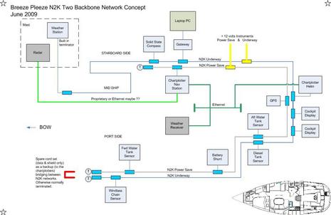
Getting back to the blue and grey backbones. The diagram below shows how the two networks are interconnected by a pair of E-80 chartplotters, themselves interconnected by ethernet cabling. I have not actually tested bridging two N2K networks this way, but the idea came from how my E-80’s are connected now. I have one each at the helm and nav station, and they effectively bridge my two seatalk networks, three NMEA 0183 network segments, radar, weather, and new N2K network (Airmar H2183 solid state compass, N2K-USB gateway), such that all the data is available throughout the boat. Should this not work as planned, my backup plan is to have a cordset ready at the bow to bridge the two N2K networks … actually I wonder if I should just take that route anyhow.
The starboard side of the network is completed and running. Although the plan was to divide up the network to support a power save mode, it has already been helpful, as I came across an issue where I want to isolate two N2K devices until a future software update. I also see this coming in handy in the future having two networks provides a quick way to debug a possibly failed device by isolating it into a simpler network, as well as having two backbones provide some redundancy and a quick place to rewire devices should a backbone cable get damaged despite my best efforts to prevent chafing.
Some big caveats … running two Mid size backbones has proven an expensive approach to wiring N2K. The expense involves not only more parts, but unlike the slender Raymarine cabling and connector heads I could have snaked through most of this boat myself, it’s proven quite difficult getting Maretron mid-size cord sets through the conduits in my boat, getting not just one but two has required help from my yard, Willis Marine, who know all the tricks to getting cable through tight spots in my Beneteau. I still don’t know how they got it through my overstuffed starboard conduit — good work David! However, this expert help adds cost, and you’re probably less likely to have plug and play if you choose to cut ends on the cable to make snaking cable easier.
Reattaching the ends is covered in Part II, in which I will start with the ingenious Maretron Field Installable Connectors for which I have a love/hate relationship.


Dan,
This looks like a great idea. I’m intrigued by the Ethernet approach. I’ve wondered if the Seatalk hs network was just a router. I’d like to plug my laptop into the Ethernet backbone instead of a multiplexer.
Mike
It is a good idea to have two separate backbones as you describe. We have done something very similar with seatalk so that the instruments can still be used when the autopilot and other larger loads are turned off.
I have my doubts, however, that the two chartplotters will relay all the data from one buss to the other, especially through the ethernet. Raymarine is very iffy with this kind of thing and it is never very well documented.
Your other approach of bridging the two busses with only the data lines is probably better, but you may find that when the underway network is turned off that the powered off devices create a load on the data lines that stop things from working reliably. We found this with seatalk.
I would suggest making the connection with some kind of relay that only bridges the two busses together when the underway network is powered up, and otherwise terminates the powersave network.
Seems like you could have tested whether or not you’re going to be able to bridge the two networks BEFORE you spent all the money to wire them both into your boat. The way it is now you might have no GPS in your BLUE network.
From the looks of things the only think you need on both segments is the GPS. If you can afford two chartplotters that are probably max 10′ feet from each other you can afford a couple hundred on a GPS antenna and not have to deal with the fragility of your home made bridge.
I have no illusions will directly bridge the two N2K networks, rather the e-series will internalize the information from one N2K network (e.g. boat speed = 2.00 knots), pass it over the ethernet in another format, and it arrives on the other N2K network (and potentially seatalk and 0183 networks as well) after being retransmitted.
So … I would not expect any PGN’s the e-series does not recognize to be bridged between the two networks, which would mean any attempts to configure an N2K device or perform a software upgrade, must be done by devices on the same backbone. If a device is configured via PC, that’s easy, I plan to be able to easily move the gateway between networks, otherwise a power off/on sequence add the bow connector temporarily engaged would create just one network end to end.
I have been giving thought to just having the bow connection in place, but Chris has given me another concern to check out first … he wrote that the devices on the unpowered bus can put a load on the data wires. I suspect the impedance / signaling design of CANBUS would decide this without experimentation. Is it just like having six TV’s at home, five of them off, and the remaining TV has no problems? Can anyone weight in on that ?
Another consideration for a permanent bow connection, what’s the best way to avoid a ground loop, if I am choosing to leave power and ground disconnected at the bow between the two networks, do I …
(i) Leave the shield disconnected at the bow
(ii) Leave the shield disconnected at the under way power tap ?
Hi!
Interesting approach. In the article you place the weather sensor on the gray-bus, but in the picture it’s on the blue. (Simply a typo?)
I would prefer to connect the Weather sensor to the gray-bus. As I usually monitor the weather closely when at anchor. Especially the wind angle.
Regards, Victor
Are you eliminating all Seatalk(1) devices from the boat?
I have a challenge with the fact that documentation says not to conenct both N2K and Seatalk(1) at the same time to a SeatalkNG network. Conencting the Eseries to N2K via SeatalkNG-N2K adapter means no Seatalk(1) devices.
That would be easy, except that I have a very nice wireless autopilot control that is ST(1), and the Seatalk-PC-NMEA bridge that is ST(1), and also some ST80Maxiview displays and their remote controller that are ST(1), and so I’m not supposed to be able to use NMEA2000 if any of these are connected.
Do you simply have no Seatalk(1) items? I don’t see speed or depth transducer pods on the diagram.
Yes on seatalk I have connected depth, speed (actually I am using an ST70 speed pod on NMEA-2000 the last two weeks), and seatalk autopilot that are not in the N2K diagram.
And not just those, I have numerous seatalk (GPS, autopilot, depth, speed, autopilot remote) and nmea-0183 (Airmar PB200, VHF radio, autopilot fast heading output, autopilot nmea0183 input) devices on Breeze that are connected to each of the two e-series that work together collecting and distributing information across my boat (e.g. boast speed from my tri data display (seatalk) network appears on my N2K and 0183 connected electronics for example).
Check the documentation your referencing, I can’t imagine what you read to lead you to a conclusion other that these can be easily intermixed.
Victor … the entry is correct, perhaps a little confusing. The weather receiver is what I look at while at anchor, it’s connected to the ethernet and goes into the single chartplotter (nav station) which I would have turned on at anchor. The receiver provides doppler radar images, NOAA forecasts, and more.
Could easily make a good case for wind direction and speed (barometric pressure, air temp, etc.) to be on the gray network … since the two network backbones are side by side, I could easily make this change on the fly if I desired.
Victor … on second thought, that’s a pretty good improvement, the weather station will be moved to the gray network and be available as well as the weather receiver.
Why not separate the two legs with one power tap to separate breakers. If in fact you are using the Maretron Power tap this can be done. I found a post on Maretron’s Knowledge Base describing the connections of their power tap . This will help avoid a gender issue on the network.
In reference to the impedance issue the data pair does not power the transceiver the power pair does. If a transceiver is inactive this will not affect the overall condition of your transmission lines.
Un-hooking the shield decreases the path of stray voltage drain from the cable allowing noise to increase.
When I first saw this post, before it was published, I asked Dan why he didn’t just separately power each side of the same backbone to achieve his goal. The answer is that the underway and non-underway devices don’t line up conveniently.
But I’m told that this technique works fine, if you can physically arrange the gear on each side of a split power tap. Unpowered CANBus devices purportedly do not cause any drains or problems on the powered part of the network.
Whereas Dan will have two backbones with split powertaps and may likely connect them, he may end up with an N2K network with four power segments. I believe this perfectly legal as long as they share the same ground, and I think he’ll be able to power any one or two or three segments. I’m hoping he experiments (which is part of design goal anyway).
I would like to say I am experimenting going forward, but that might be a wild claim.
This isn’t as off the wall as it might look, especially if you take away one chartplotter and install the cord set at the bow of the concept diagram shown (cord set bridges two data wires only, note both yellow power taps share power ground and shield). Let’s call this the “one chartplotter version” of the same concept.
Now looking back at the once chartplotter version of the network concept diagram, move the two power taps to the bow, make it just a single power tap, with one side of the tap on an underway circuit breaker and the other side of the same tap on a powersave circuit breaker … does the network look at all experimental ? If I had done it that way, does it provide a clear benefit in your mind over running a single backbone ? Does it look like a no brainer that it would work ?
Hi Ben,
Are there any SeaTalk1 instruments on your network? If so, how have you managed to get their data onto the NMEA 2000 network?
Jeff, I don’t have SeaTalk1 one my N2K network but Dan (who wrote this entry) does on his. Sort of. As he explained in a comment above, he has SeaTalk sensors connected to his E-Series MFDs, which then bridge at least some of the data over to NMEA 2000.
A number of different brand MFDs do this sort of bridging but it’s usually not well documented and uncertain. I have used a Raymarine pod to turn SeaTalk1 wind sensor output into N2K messages, and it worked OK:
https://panbo.com/archives/2008/03/more_st70_the_calibration_conundrum.html
Jeff,
Yes, I have lots of seatalk1 transducers (speed, depth, wind), ST60/ST60+/ST70 displays, autopilot, and autopilot wireless.
Dan,
Following up on the SeaTalk question: When I added an NMEA2000 network to my existing Raymarine SeaTalk gear (E120 plotter, wind, speed, depth, GPS, Autopilot), I hoped/expected that the E120 would bridge *all* of the SeaTalk data onto the NMEA 2000 network so that my Maretron N2KView software could see it. This isn’t happening on my boat. In fact, I see none of the basic sensor data. I know that the NMEA2000 network is working properly because I *am* seeing engine data on the E120 that is being created by an NMEA2000 box from Maretron.
Do I have to wait for the Actisense NMEA0183 to NMEA2000 bridge to be released?
Does anyone know, for certain, why Raymarine indicates that connecting a Seatalk(1)+Seatalk ng to a N2K network is not recommended?
Or, who has these three network types connected aand sharing information?
In response to a question above from Jeff Shukis : Yes, I say with certainty the seatalk data is bridged from my e-series between the seatalk and NMEA-2000 bus. I was able to observe the data from my seatalk instruments on the NMEA-2000 bus using the Airmar NMEA-2000 to USB gateway and WeatherCaster software. Specifically I saw depth, speed, water temp, heading, and GPS position.
Does anyone know if you can generate data in a NMEA 2000 network from the Maretron engine data box and a NMEA 2000 transducer (speed/depth), then put it into a Raymarine Seatalk NG network, add say wind data from an ST-70 TD Pod then put it through an ST-70 to feed ST-60 displays (no data creation just reading) via a Seatalk 1 network? Or is Raymarine being that harsh about creating connections between NMEA 2000 and Seatalk 1. I guess one could just use a NMEA 2000/0183 bridge to do the same along with a NMEA 0183 /Seatalk 1 bridge (E85001)? I would hate to start adding more Seatalk 1 pieces when they are being phased out and if Garmin buys Raymarine.
This article aged pretty well. In retrospect, I would comment that the 2nd backbone was entirely unnecessary. As much as I tried, I never put it to use. On my next boat I just have 1 backbone.
Hi Dan, I had the same intention when I stripped all the test systems off Gizmo along with the second N2K network. But after the redo, and a month or so with only one network, I went back to two. The change solved some issues — like the fly bridge autopilot controller showing data but not responding to commands — and I like having the redundancy again. It was a pretty busy single network, however, and included devices from many different manufacturers.