
Adventures in NMEA 2000 Wiring, Part II
Guest Entry by Dan Corcoran —
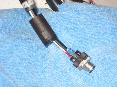
Above is a picture of a Maretron field attachable connector that I have installed on Breeze Pleeze at the end of a Raymarine spur cable. The connector provided me a reliable way to connect a Raymarine ST70 and Raymarine ST70 N2K Speed Pod onto my Maretron backbone cable, where it is part of a multi-vendor N2K network (as discussed in Part I). In this picture I have opened up the connector to expose it’s internals for you to see.
This product is useful for connecting products from other N2K cabling schemes as well as creating custom length cabling in the field, after one cable end has already been snaked through the boat and the correct length has been determined.
This product accepts each of the stripped ends of a five wire N2K cable, into tiny sockets that get a positive lock on the wire with small screws, much like you would have on a 120VAC marine outlet or plug, and now on some 120VAC switches and outlets for home use. This connector is so effective, I wouldn’t hesitate cutting off a pre-made end of a backbone or spur cable to make it easier to snake and/or shorten it up to the ideal length for my boat. Shortening up backbone and spur cable can be both a weight savings and power drop savings, especially since I tend to order cables that are 4-7 feet too long as pre-made cable is sold in lengths of 1 meter.
To reassemble the connector pictured above, I screw the bottom of the protective case over the connector, slide the strain relief down, and screw the strain relief onto the case. The strain relief compresses as I tighten down, a design that provides compatibility for a wide range of cable widths.
The positive feedback on the terminal screws and the strain relief design yell quality and long life, both apart and as a finished assembly ready to screw into the backbone. Something that could be better is the instructions. There are none actually, unless you count the picture on the bag. A recommendation on the sequence of attaching the five wires would be especially helpful, something like:
(1) Don’t forget to slide cable relief up the wire first
(2) Connect the ground lead before the others (the ends of a stripped ground wire become quickly separated if you handle the other wires first)
(3) Leave the center (tall post) wire for last. (For some reason the center location and tall post seemed to scream out “me first”, but alas, you will find the other wires more flexible to work with if you save connecting the short red wire to the tall post for last.)
I am sure that someone who has installed more than two, can further expand upon the instructions.
The other amazing thing about the connector is it’s size. Some engineer found a balance between the absolute smallest size to make this, and what my clumsy big fingers can handle (my thumb is bigger than the whole connector). If this was a touch smaller, I couldn’t do it. I was able to balance the entire connector in my hand while I screwed on the terminals. A small screwdriver with rotating base was very helpful, as I could balance the base of the screwdriver in the palm of my hand, and rotate, one handed, while fingers from both hands hold the wires and connector secure.
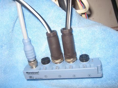
In the bottom photo, are two finished field installable connectors mated to a Maretron Micro Multiport. The Multiport lets you extend one drop cable to additional components either now or in the future, though the total drop — backbone-to-multiport cable plus multiport-to-device cable — still can not exceed 6 meters (for Micro or Mid size cables). The effect is somewhat similar to the Raymarine daisy chaining I like (some Furuno devices and most all Simrad Simnet devices also support daisy chaining). Except that a multiport is perfectly legal under NMEA 2000 cabling rules while daisy chaining is not, because the NMEA does not like to see one device’s data passing through another device.
Both approaches greatly simplify the pre-planning of an N2K network, so you don’t have to think too hard about what N2K devices might be installed five years from now that might require a backbone to reach a particular space in your boat, when just a spur will do, both now and in the future.
One best practice when designing N2K backbones for a sailboat, is to start one end of the backbone at the bottom of the mast, so you have flexibility later to extend the backbone up to the top of the mast (having one end of the backbone in the mast overcomes spur length limitations). Some products like the Airmar PB200 even have a pre-made cable available to be the last segment of such backbone with a terminating resistor built in. For sailboats, and I suspect most power boats, the other end of the backbone ends up in a remote end of the boat (mine ends at the bow) rather than at a helm or console where there is a cluster of N2K instruments.
In Breeze Pleeze, I could have snaked the middle of the backbone up and back down some dedicated conduit to my helm, a detour of 36 feet, but there is a better way.
The Maretron Micro Multiport can be positioned in the helm and connected to the backbone with a single spur, providing access to 4 devices in my helm. It effectively shortens the total amount of cable used, dramatically reduces the backbone length and any associated power drops are limited to the devices at the helm. In my case, the micro- cable I use takes 30% of the space in the conduit then two mid-sized backbone cables otherwise needed to bring the backbone up and back down.


I like the field installable connectors too, but I haven’t been able to use them on a drop cable for the Garmin GMI 10s and the Garmin N2K GPS sensor. They work fine along the backbone, but as soon as I use one in a drop, the device doesn’t show up. I’ve tried using Garmin’s and Maretron’s tees. Anyone else run into this problem?
That’s odd, John; I can’t picture why the field attachable connector wouldn’t work with any kind of N2K cable. But then again I don’t think I’ve ever cut a Garmin cable; does it have the same wire color coding? Did you try the same run with a non Garmin drop cable?
Note that NMEA recently issued a notice about how early Garmin N2K cables were not NMEA 2000 certified (pdf here: http://www.nmea.org/Assets/technical%20product%20update%20200901.pdf), and rumor has it that even Garmin’s certified cables are not great in terms of impedance and shielding. I hear that there’s also a lot of N2K cabling being sold that isn’t certified at all. I’d be careful on this score, particularly with large 2000 networks.
I used Maretron field-attached connectors for my entire “mid” backbone – they are that solid. One tip I learned: cover the (otherwise bare) ground wire with a length of shrink tubing. Why? Looking at your photo above, an aggressive twist on the cable could bring the exposed silver ground wire into contact with the exposed screw of the center wire. Of course one “shouldn’t” be running around giving cables a nasty twist, but it could happen. Why take the chance?
Jeff
Ben; I have a fairly large suite of Garmin plotters, Navionins Class B AIS N2K, and most Garmin N2K deivice sold on my network. I have not had a single problem using the Garmin field installation connectors and the pre-made connectors. The list is the following a 4212, 4210, Navionics NAIS300L, GPS17X, 3 – GFS-10’s, GWS-10, GXM51, 2 Garmin VHF200’s and GMI-10. I have split the network but everything works as it should. I have had no glitches, my AIS self alarm is fixed and I can view AIS A & B vessels. The static data on Class B is missing the ships name only. I also have a 3205. GSD22 & GMR-18HD on the Garmin network so are the 4212 & 4210. I have a KVH1000 position sensor on NEMA0183 that all 3 plotters see also a Furuno NX300 Navtex receiver on NEMA0183 and my Mercruiser System View 5000 displays on the 0183 network. I am running software version 5.3. All is running very good here. I am very happy. With the exception of the Navionics AIS B unit all T’s drops and terminations are Garmin. On the video I jave a FLIR Mariner II and 2 200 series plotter. I love my Garmin stuff!
Bill Lentz
Bill, What do you mean “split the network”? The NMEA 2000 network? Why?
I like the idea of using heat shrink tubing on the bare ground lead Jeff. Although I may not be going back to enhance the existing two connectors (I feel comfortable enough that the strain relief is going to prevent the internals from twisting) this would appear to be a very good practice to extend the life of the backbone.
I will update the instructions above to add your idea Jeff! Any other improvements to the field attachable connector instructions anybody ?
Have used the field connectors as well in the initial installation of a Maretron speed/depth transducer and a Furuno FI-50 display at the helm.
These were the first connections into a new “mid” backbone I installed after a rewire this winter. I was concerned about cutting into the backbone and making the connect, but with cutters in hand I jumped in.
To my joy I powered up the system and have been running flawless NK2 all summer. Looking forward to building onto the network now that the option to add other devices is mostly a field connection away. Thanks for the great post.
Steve
I too really like these Maretron connectors, and keep a bulk spool of Maretron cable on hand rather than pre-made cables. The installs are cleaner without the excess cable coiled up.
Question: What are the lists thoughts on tinning (soldering) the ends of the cable before inserting it into the connector?
I normally tin all my cable ends just is a practice i have always done.
i prefer the Omron connectors (i source directly from Omron)
they are the connectors furuno use on their SC-30 and are slightly smaller than the Maretron field connector (same wiring)
Andy – Could you supply part numbers for the Omron connectors?
Thanks,
Jon
My take on “tinning” the wire ends: Yes!
I tin just the end of each wire, working very hard to ensure that I don’t stiffen a significant length of wire. Don’t worry – I do make sure that I get good solder flow – no “cold” solder connections. This bit of solder keeps the wires neatly together when making the connections, something that I very much like, especially when doing wiring in the limited access/limited visibility world of boat wiring.
One more tip: Apply a little Corrosion-X (or your favorite equivalent) to the wire ends with a Q-tip before assembling. I did this to reduce the liklihood of seeing increased resistance over time as corrosion builds up on the copper wires, especially in the (strangely) untinned Maretron power wires.
To summarize: Cut wire lengths exactly, cover the ground with shrink tubing, tin the ends, dab with Corrosion-X, assemble carefully to ensure strain relief, test thoroughly. If this sounds like overkill to you, you’re probably new to mixing salt water and electronics!
Thank you for your suggestions ! Any more before I update the entry ?
Also, I tried tinning some wires on my latest connection this weekend. What’s the trick to get the solder flowing before melting the insulation ?
Dan,
Check to make sure that you have the right kind of solder – thin, flexible, flux cored, and made for soldering electronics. With the right setup, it should be trivial to solder without melting the insulation.
I heating the tip of the wire for about 7 seconds (soldering iron dependent) and then apply solder to the wire (not the iron) and watch it flow into the strands.
Re: soldering — also make sure that the wire is clean and corrosion-free. Dirty or oxidized wire will not take solder.
Having a little solder on the iron will help transfer the heat to the wire, but as Jeff says, once the wire is hot apply more solder to the wire.
I see. I was putting the iron 1/4 of the way up from the tip of the wire expecting the tip to heat and draw the solder up before the insulation melted.
One more soldering hint: If the wire is heavy-gauge a too-small iron won’t deliver enough heat. Within reason, a bigger iron is better, since it can heat up the copper wire quickly, allowing the solder to flow before the insulation has a chance to get too hot.
If we’re talking about the small wires that go into one of these NMEA-2000 connectors, just about any soldering iron should do the job well.
I can’t picture why the field attachable connector wouldn’t work with any kind of N2K cable. But then again I don’t think I’ve ever cut a Garmin cable; does it have the same wire color coding?
One other thing I have found while making up perhaps 10 field-attachable connectors…depending on the diameter of your cable, the rubber collar inside the strain-relief plastic “cage” may not be able to be compressed much, and if you try to compress it further it will not compress uniformly and the cable will be pushed off to the side. If you look at the jacket of your cable you will see the little indentations left by the prongs of that cage, and even without the rubber collar, the cage will hold the cable securely and provide strain relief. I also use cable ties, screwed to something solid, and fastened around the cable on one side of the connector and the tee or whatever it connects to on the other side.
I cut a Garmin cable in half and wired it to a DB-9 connector for my hacking project. This Garmin cable had the standard color code.
The connector threads seemed to be prone to cross threading, so I now have the Garmin cable attached to a short Airmar cable so that it can be connected more easily.
Jon
Jon TC, are you talking about field connectors in general or the Maretron connectors ?
I know I was very impressed with the mechanical aspects of the strain relief (twist the screw and it seems to apply pressure uniformally around the cable) and that it seem to handle a wide range of sizes including the very thin Raymarine cabling. Did I miss something ?
If there is nothing real special about n2k cable can I use my existing cable for my wind sensor. I’m replacing a Navman Wind with a Garmin system and I could just install the field connectors on the existing 5 wire cable and not run new cable down the mast.
It would make the job a lot easier, but if I would loose anything I’ll just run new cable.
There are some special characteristics to N2K cable — mainly to do with impedance and EMI protection. I suppose you could try it with existing cable but you may have change if see problems. Suggest you read Garmin’s booklet on N2K network design; you prolbably need to terminate one end at masthead.
Hooked up another sensor yesterday, I love how this N2K always works every time I add a device or modify the wiring, even when as I did this time, got down and dirty and used a maretron field attachable connector to shorten up the devices wire (takes 10 minutes and some precision to cut and strip wires)
The downside, this is not furthering my electronics hobby one bit. No N2K troubleshooting skills are being developed, no war stories to share, anyone with basic skills can do this, especially if they go with the included connectors.
Way to go N2K.
Me too! Installed an Actisense EMU-1 analog engine data converter over the last few days and now have Gizmo’s gauges also sending PGNs to the boat’s NMEA 2000 network. Not a trivial install, and not perfect results yet, but I’m now convinced that I’ll be able to put the old guages in less desirable real estate while getting better looking live data, more flexible alarming, plus engine data logging. Cool stuff.
Questions for anyone who combines Raymarine products with a Maretron NMEA2000 backbone
I have built my NMEA-2000 backbone, written about in Panbo above, and diagrammed here in Part I of this series:
https://panbo.com/assets_c/2009/07/BreezePleezeTwoN2K-711.html
… with expectation any devices I add would be done with a spur cable either off the backbone or from a Maretron Multiport (pictured above) placed in some strategic places like my helm.
I am getting tripped up that some of the Raymarine components are designed to be placed in the middle of the backbone, having the backbone enter a blue connector on one side, and exit the blue connector on the other, such as the itc-5 and the Seatalk 1 to Seatalk ng converter.
As I didn’t run the backbone up to my helm, choosing instead to had 5 port Maretron Multiport, but my seatalk wiring is exactly in that spot, I am challanged to install either an seatalk 1 to seatalk ng converter like this one
https://panbo.com/assets_c/2010/08/Raymarine_SeaTalk-STNG_Converter-2701.html
The helpful folks over at Raymarine wrote to me “Dan,The iTC-5 is not designed to be installed as a spur. As such, it may be installed at one end of the backbone or within the middle. To do so, a SeaTalkng Backbone Cable will need to be spliced to the Maretron backbone cable … simply match the colors of the wires within the respective backbone cables.”
Some questions for the Panbo forum
1. Each of these devices has two back bone (blue) connectors and a spur (white) connector. Is Raymarine advice above correct, (i) must I insert them in the middle of my backbone, or can I connect these devices using the spur connector and not use the backbone ports? (ii) if I can use just the spur connector, should I put terminators in the two blue connectors or leave them empty?
2. Is it ok to to have a backbone that alternates between Maretron cabling and Raymarine Cabling, back to Maretron cabling? (other than the obvious, voltage drop considerations of the thinner cable, is there any impedance issues ?)
3. Unrelated, my new Raymarine evolution autopilot, with the abysmally short custom spur connector does not reach my backbone either. Normally I would modify a raymarine cable to do this, by adding a field installable maretron connector, but evolution has this strange connector the autopilot end that is not available in longer lengths. What is an acceptable way to extend a spur cable, can I just screw in a maretron micro cable into my field installable maretron cable, to make the autopilot cable longer?
Thanks, Dan
Dan, I think that Ray has simply built a CanBus Tee into the ITC-5 as a convenience. I’m pretty sure that you can put a field attachable male N2K connector on either an STng blue or white cable and it will make the ITC a working device on a spur/drop cable. Do not add extra terminators to your network but do seal up the unused ports in some way (I’ve used Rescue Tape).
I also think that you can extend the AP’s STng cable with a field attachable and a regular N2K cable, as long as you don’t violate the 6m drop maximum.
But then again, I haven’t done either of these things, so good luck and please report back 😉
(I have mixed STng and DeviceNet backbone cable without any issues. STng actually has power wires gauged like Maretron MID, I think.)
I recently had my 1st opportunity to use this Field Attachable connector and referred back to the great tips here, thanks to all.
Anyone use ferrules instead of tinning like this:
https://goo.gl/photos/HK8Yua6EsxCrqWHV9