
N2K, cable mixing not a big woop
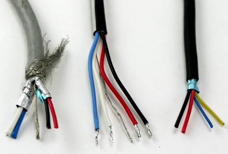
My macro photography needs improvement, as does my cable stripping, but I think this shot makes a point. From the left, the cables above are standard (DeviceNet) NMEA 2000, SeaTalkNG (aka NMEA 2000), and SimNet (aka NMEA 2000). Notice the similarities. The internal wires all adhere pretty closely to the NMEA color standard, which goes as follows, “Net” nomenclature included:
White: Net-H, “high” data signal
Blue: Net-L, “low” data signal
Bare: shield
Red: Net-S, 12v DC power supply
Black: Net-C, 12v DC ground
So the SimNet cable is slightly odd–the Net-H more yellow than white, and the shield apparently just foil, not wire–but then again it’s the one that’s truly skinny and light. I didn’t have LowranceNet Red or Garmin “NMEA 2000” cables to strip, but I wouldn’t be surprised if their wires were also color matched, and it doesn’t matter much anyway because they are both plug compatible with standard N2K connectors and devices.
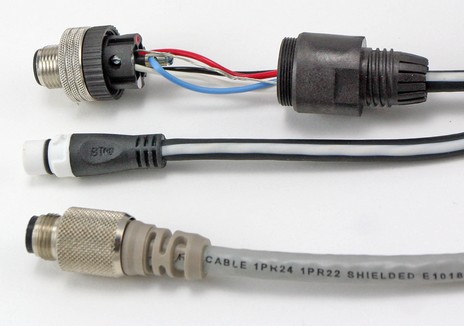
At any rate, the matching colors made it very easy for me to throw a Maretron micro-size field-attachable male connector (itself neatly color coded) onto the SeaTalkNG “stub” cable (below). Thus I was able to hang an ST70 display off the lab’s ever-growing test N2K network. (And–bada bing–it powered up and slickly displayed about every data PGN available, but more on that later, this is about cables.) However, you don’t have to make your own patch cable to marry SeaTalkNG (or SimNet) to standard NMEA 2000 cabling or devices. Raymarine later sent over both male and female adaptor cables and they’re available for sale. In short, N2K cable mixing is not a big deal. Later I’ll post more about the SeaTalkNG design, maybe even theorize about why it exists (short answer right now: no idea!). But before I close, let me draw your attention back to the standard cable above. Note the exterior braided shield plus the additional EMI shielding around each of the two wire pairs. If that cable costs about what the others do, and supports more installation doodads than any other system, why not use it?
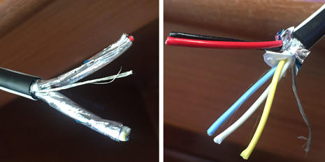
PS 11/20/2016: The good Hartley Gardner sent photos of a Raymarine SeaTalkNG spur cable recently dissected. Note the separately shielded power and data wire pairs, the extra yellow wire for certain Seatalk1 uses, and the fact that the power wires are heavier gauge than standard N2K micro wires, which reduces voltage drop.


Email notes from an interested engineer:
1. The Raymarine ‘SeaTalkNG’ cable is missing 1 or 2 points which we believe are important:
a. There really should be separate shielding foils around the two pairs (CAN Hi & Lo, and Power +/-) – so that the power noise cannot get on to the data pair.
b. The insulation on the CAN Hi & Lo (Blue and White) cables needs to be as thick as possible to help reduce the capacitance of the cable – so reducing the skewing of the signal. Not sure if this cable has less insulation on the blue and white cables (than the power wires), or its just the photo.
2. The SimNet cable is a worry – the lack of screen/drain wire will make connection of the shield very difficult for the user, and the thickness of the insulation on wires is very small – hence increasing the capacitance. If a large length of the bus was made using this wire, the 200 metres maximum bus length could be reduced considerably. If its purely for the drop cables (6 metres absolute max., 3 metres preferred max.), then I guess it may be acceptable.
3. The Maretron field attachable connector is a Woodhead / Brad Harrison connector (who were bought out by Molex last year…sad but true). Cheaper to buy direct.
Somewhat related….I am about to rewire a bunch of our NMEA 0183 system to add a multiplexer with AIS capability. Mostly short runs behind the NAV station, but a few longer runs to add NMEA to the autopilots and the second VHF radio that was never wired up before. What wire would people suggest using. I have seen a few references to CAT 5e being used as it is quite low capacitance, available, cheap, etc. I have a bunch of CAT 6 cable laying around from wiring the office (this has a plastic + running through it to separate the twisted pairs). CAT 5 of course is not shielded.
How common is it to add connectors to cables? Last year I bought a Lowrance plotter, and the connectors are too big to fit inside the steering pedestal. I contacted Lowrance tech support, and they told me I cannot cut the cable, run it, and reconnect it.
I have bought a bigger diameter pedestal so the connectors fit, but if I don’t have to install it….
Barry, I surely don’t know enough to overrule any tech dept, but I do think that manufacturers are being extra cautious as we all ease into the world of NMEA 2000 networking. I’ve messed around with this stuff a fair bit now, and am regularly impressed with how forgiving and rugged the N2K data/power design is, even when not used per the manual!
If I were you, I’d certainly try a field installable connector before changing out the whole steering pedestal We are also starting to see N2K break out boxes, which I’ll discuss tomorrow.
Raymarine told me at METS that the reason they have the specific connectors that they use is so that they can be passed through smaller holes. With the Raymarine connectors the rotating bit of the connection is actually on the device, not the cable. They showed this off, with cables passing through a quite small hole. Not as small for just a cable, but still a lot better than some other connectors.
Quite smart, although it does obviously mean that they deviate from the standard.
Field attachable connectors have been used on Devicenet wiring in factories without problems for years. You just need to spend the time to do it right.
Great pictures! They bring back not-so-fond memories of stripping and soldering computer data cables to make a cable that connected from Computer X to device Y. At least it doesn’t look like any of the connectors have about 20 extra pins that nobody uses, which only exist to confuse you.
I much prefer USB cables.
I think that this is a bit of an issue with NMEA 2000, let the manufacturers specify their own connection ends and you will spend hours stripping and wiring…
Hi, I’m having som problems when connecting a Maretron Micro Field female connector to a Garmin 4008. The NMEA200 input is from a Yamaha command link (installed in our boat – 2007 model). I’ve tried to connect the original Yamaha command link cable 6Y8-82521-11 with the MARETRON female connector. But then the Yamaha speed/fuel and tachometer instruments got blacked out.. (hopefully just a fuse!)
The original Yamaha cable has wires with color codes red, blue, black and white. The only wire I didn’t quite know where to connect on the MARETRON female connector was the black one… I tried to connect it to terminal #1 (marked with a silver color code – I assumed it meant GND). But from your very good blog here I now know that the silver terminal should have been the shield… The black should probably have been connected to terminal #3, or? But this wrong wiring shouldn’t have caused the fuse on the gauges go because, or?
Could you please indicate which terminal number should be connected to the given color? The blue one is straight forward, but I think that the other could be interpreted in two ways…
Hi – So does this mean I can extend a device cable with no issues (lowrance Red Fuel Usage Sensor)?
Cheers
Adriaan, I really didn’t get into cable lengths, but it’s fairly straight forward. A micro size backbone shouldn’t be more than about 300 feet long, and drop cables shouldn’t exceed 20 feet. If the run to your fuel sensor exceeds 20′, make the extension part of the backbone. Or you can make the fuel sensor the end of the backbone using an inline terminator.
If you have a lot of devices on your N2K network, or especially long cable runs, you also need to think about voltage drop. I’ve written about it here:
https://panbo.com/archives/2009/03/nmea_2000_power_problem_part_2.html
And Lowrance, Maretron, and others have all produced NMEA 2000 installation guides that you can download.
Interesting. Looking at Simnet how does one connect the shield when the simnet connectors are all plastic outside?. Help would be much appreciated
I have a C120 chartplotter. I had a raystar 125 GPs anntena connected on the seatalk network and it finally quit. I bought a RS 130 GPs anntena and it uses the seatalk ng network. Does anybody know if I can cut the seatalk ng cable and connect certain wires to the 3 wire seatalk network cable like I did for the RS 125?
Don’t do it, Mike. It’s possible to mix different forms of NMEA 2000 cables, as this entry discusses, but regular SeaTalk and NMEA 0183 are quite different in many ways. Depending on your situation, I think you need to get a SeaTalk or 0183 GPS instead of the RS 125 or a NMEA 2000 to NMEA 0183 gateway like the Actisense NGW-1.
Working on a Simnet autopilot. I would like to interface to my existing Maretron Electronic compass that is on my current Maretron backbone as a drop.
If I connect, as a drop, to the simnet 3 terminal “joiner” using the NMEA 2000 to simnet conversion cable, will the simnet be then powered from the Maretron network (which would include the AP24 control head and RC42 computer.
Can I add a simnet power source to the 3T simnet joiner ?
Or is there an issue with multiple power supplies ?
You have to let the 3 way joiner connect to the backbone – think of it as a nmea2000 T-fitting.
If you are using std. nmea2000 connections in the boat now, the why not cintinue doing that?
Only differece between simnet and std. nmea2000 is the plugs.
And only 1 power source on the network.
Dadidoc’s question wasn’t entirely clear to me, but one important point is that the Simrad AC42 (sic RC42?) computer needs its own power source. It drives the steering system from this, so cannot be powered by the N2K network.
It is unclear whether he meant RC42 compass or AC42 computer.
And yes, the Simnet “joiner” will be powered by the N2K backbone when connected to it with a conversion cable.
Mikkel is right that SimNet and standard (Maretron) N2K cabling are very similar, but you do have to think about your network architecture.
If the total cabling from the Maretron backbone to the AP24 and ACxx (not sure you meant RC42 because that’s a compass) doesn’t exceed 20 feet, you can think of them as a multidrop. Remove power and terminators from the SimNet section.
But if the SimNet ‘branch’ is longer than that, I think you should redesign the Maretron backbone (and get more adaptor cables) so that the Simrad gear drops off it.
If you want to keep two separate networks with their own power, backbone, and terminators, then you’ll need an N2K Bridge or Extender, which can pass data only to each.
The Maretron network guide has deeper info on maximum backbone and drop lengths:
http://www.maretron.com/products/pdf/Network%20Installation%20Guide.pdf
1. Sorry, I did mean the AC42 Autopilot computer vs the compass.
2. I did see the Maretron NBE100 network extender, but big bucks ! Would have been nice to have a separate network under own power for autopilot functions and be able to even have a second compass source on SIMNET. But not today.
3. I will stick with single power source on my current Maretron backbone.
4. Will create a drop from my Maretron backbone to the to the Siment T connector (24005860) using adapter cable (24005729). This should feed heading,depth and all the other PGNs to the control head and computer.
5. Will run Simnet to the control head vs having it drop to my maretron backbone just in case I have integration issues and need to have a separate network for autopilot – hope not. Need to keep this length of a drop within spec and not use a super long cable.
6. Will run simnet, single end connector, and hardwire other end to the AC42.
7. Will hard wire RF300 to AC42 computer, but keep my current RAA100 rudder angle indicator on network. My have two different sources for rudder angle and the computer will probably broadcast PGN 127245
as does the RAA 100 from the simnet. May need to disconnect RAA100.
8. Will then look at network analyzer boat file and see what is happening on the network so as not to get my Coastal Explorer software confused which gets network data from USB100 pass through.
9. Hopefull that autopilot will play nice with SSC200, GPS200, DST100, DSM250 and WSO100.
1. Will the AC42 computer broadcast rudder position on the network once it calculates it from the hardwired connection from the RF300 to the computer ?
2. I currently have an RAA100 rudder angle NMEA on my network – wondering if I will now have two PGNs on network ?
3. It is my understanding that the AC42 Computer MUST have the RF300 and it will not use something on the network( even though they show in the manual that the Simrad RF25 would work with steering computer. ) Hmmm, wondering why the Maretron RAA100 PGN would not be useable – but something hardwired to computer must be better I gather !
Yes, the AC42 broadcasts a Rudder PGN, but there may be two different PGNs with rudder info. What I’ve observed when I bridge the SimNet and N2K networks on Gizmo is that some instruments like the Garmin GMI10/20 and Raymarine i70 can see the rudder info but others like the Furuno RD33 can not. Not sure what’s going on.
But the good news is that I can bridge a ton of PGNs including many duplicates without any major issues. I doubt you’ll have an issue combining what you have with Simrad stuff, though I’m not sure about having two rudder angle sensors. Plus I can’t think of a good reason to have two of them active, so worse case may be that you’ll only plug in the Maretron one if the Simrad one fails.
I am using the rf25 rudder sensor with my simrad ac12 autopilot, no issues what so ever, and rudder angle can be displayed on my dsm250.
Thinking about making a change and using less SIMNET cable – preferring to stick with my Maretron cable for all drops. Will need to buy a second conversion cable.
So,
1. Will create a drop from AP24 to join my maretron backbone closer to AP24 in cockpit and elimnate a 18 foot run from aft steering quadrant. This will be a second planned drop.
2. Will still have a drop from backbone to the AC42 computer as earlier planned but will do without the 3 T joiner where I had chose to split out and run simnet to control head.
3. Also will drop my maretron RAA100 and stick with RF300 and respect SIMRADs claim for frequency algorithms and rudder response.
appreciate the knowledgeable folks on this forum !
thank you !
Sounds like a good plan, Dadidoc. Simrad hasn’t made a big deal about it, but it’s obvious that they are gradually moving to standard N2K cabling. It’s very likely that new autopilot heads will have standard ports.
Note though that rather than buying a second adapter cable (and a SimNet-to-SimNet ‘joiner’) you could just cut off the female end of a standard N2K cable and attach the wires to the AC42.
Great information here! I am installing a TP22 on a 30′ Mercator sailboat using the AP28 on the Simnet backbone. Will the AP22 pick up the compass info from the TP22?
Also is there a wiring diagram somewhere for Simnet?
A small update – I stripped a RayMarine SeaTalkNG spur cable today and discovered they are a little different now – the power and data wires are separately shielded, with a common drain (“shield”) wire, and they added a yellow wire to the white & blue data bundle, which is labelled “SeaTalk1” in their diagram. I’ve sent pix to Ben, maybe he can post them here.
Thanks, Hartley. The photos are added as a PS to the entry (and it was a bit of adventure editing an entry so old). I also noted that SeaTalkNG uses larger gauge power wires than standard N2K micro cables, which is good in terms of voltage drops, sort of like using Maretron Mid cable:
https://panbo.com/archives/2009/03/nmea_2000_the_power_problem_part_1.html
https://panbo.com/archives/2009/03/nmea_2000_power_problem_part_2.html
Hi Ben,
I’m really confused by the yellow wire in the Seatalk NG Spur cable. Why would an STNG cable have a Seatalk 1 wire in it?
I am in the process of extending a spur cable between a Raymarine A70D MFD chart Plotter/GPS and an ST1/STNG Converter.
I don’t need power to the Plotter via STNG (it has it’s own power supply), only data.
I only have 4 cores available for the extension so I think I can leave out the red cable.
I don’t think I need the yellow one, as this is an STNG connection and the Yellow is apparently for ST1.
So I’m left planning to extend the Blue (data low), White (data high), Shield and Black (ground).
Do you think this will work?
For data high and data low, do you think this is a pair for communication (e.g. signal and ground)? Or are high and low referring to data rates?
When I hook up the STNG cable via the STNG/ST1 converter to an ST1 cable and test for continuity, the ground (black wire appears to be connected to the ST1 shield/ground.
I’m assuming ST1 uses Yellow and Shield as the data pair and red for power – so my guess is the STNG uses the ground (black) and one of the others for the data pair.
I suppose if it doesn’t work with the wires I’ve chosen, I can try swapping connecting the Yellow instead of White (or blue?).
Interested to hear your thoughts.
I’m reluctant to ask Raymarine, because they will probably just tell me to buy a longer spur cable – but I don’t have space for an additional cable (which is why I’m trying to use the 4 spare cores in an existing cable).
Interested to hear your thoughts.
Cheers
Dave
Hi Dave, I think you’re over thinking it. I don’t quite recall how the yellow STng spur cable wire works (it’s on Panbo somewhere) but you don’t need to think about it because you’re just trying run a regular 4-wire drop (spur) to a regular STng/N2K device (which happens to be taking care of the ST1 data conversion).
So just splice white to white and blue to blue for the data (high and low about voltage levels) and red to red, black to black for power. And, yes, you do need the full power connection I’m pretty sure. Even when a bigger device like your MFD is mostly powered by separate cable, I think that the internal STng/N2K section still gets its power from the network.
Hi Ben,
Thanks for the quick reply. You’re dead right, over-thinking could be my middle name. Anyhow, hooked up the red and it’s all working just fine, no need for the yellow.
Cheers
Dave
having a problem finding the crossover/cable connecting the rj45 on sr6 marine weather receiver to a series “a” raymarine ( also have a c series and a E80 for some reason,,i’,m just learning) i could add a 5 waw seatalk to backbone however i have a open “stng” port on series a , could that work ,can’t find a connector or adapter
Ed,
STNG (Raymarine flavored NMEA 2000) and STHS (Raymarine flavored ethernet) can’t be joined. If what you need is a crossover cable for Seatalk HS Raymarine part #E55060 is a crossover coupler that can be used to turn standard cables into crossover.
Ben S.
I read through this thread carefully and just want to ask for clarification as to how to wire a N2K field connector to a Simnet cable? Do you ignore the lack of a shield wire or do you try to roll the foil in the Simnet cable into a wire and make the connection to the N2K field connector?
Hi George. I think that you could probably get away with ignoring the foil shield connection, but these little SimNet cables are not really suitable for field connectors. A much better way is a factory-built adaptor cable, with either a Micro C male or female end depending on what you’re doing. Example:
https://www.simrad-yachting.com/simrad/type/accessories/cables-connectors/cable-micro-c-male-to-simnet-0.5m/
They also sell SimNet Joiners if needed:
https://www.simrad-yachting.com/simrad/type/accessories/cables-connectors/simnet-joiner-yellow-wo-terminator/
What I have is a RC42 compass that I am trying to add to my N2K network. One end of the wire is hardwired into the RC42 and the other has a cut end. When I peeled back the insulation I found the 4 colored wires – white, red, blue, and black and also a bare bunch of thin strands. I rolled the strands to form a single wire. I then used my Maretron field connector and wired it up based on the numbers on the connector and the Maretron guide including the bare strands. I then connected to a regular drop line and T connector and added it to my back bone. Seems to work.
Its temporary as I intend to replace the old RC42 in the not to distant future.
Glad it worked out, George, and once again affirmed the entry title, “N2K cable mixing not a big woop” 😉
Ben Ellison, just wanted you to know that even after 11 years, these conversations are still very helpful. Thanks for your time.
Thanks, Ricardo. It’s nice to know that technical research and explanation I put together long ago — 16 years ago, actually — is still useful.
Hi Ben, Thanks for your 16 years of info. I’m also learning from these threads.
I’ve just installed RM Autopilot EV100 and wanting to join my ST60+ Wind ST1 to STng. I have the correct red, black, yellow plug and cable to a white STng spur. Do you know if I need the ST1/STng convertor or does the standard STng white and blue connectors link the yellow data to the appropriate backbone / N2K wiring?
Sorry, Blake, but wires alone can’t make ST and STng compatible. The data formats and the electrical transmission schemes are both different, so there has to be a converter/bridge involved, either standalone or built into something else. Probably the most straightforward solution for you is Ray’s E22158 Seatalk 1 To SeatalkNg Converter Kit:
https://www.hodgesmarine.com/raye22158-raymarine-e22158-seatalk-1-to-seatalksupingi.html
At the back of the manual is a list of the data types that get translated in each direction. Wind info should certainly get to your new AP, and there may be other benefits depending on what data is in your ST and STng networks and what the various screens can display:
https://raymarine.app.box.com/s/rvhycb6x1brzo64921k5tsqwv2ica3j6/file/31974304017
Finally, this converter worked well for me 14 years ago and is no doubt better now:
https://panbo.com/raymarine-st-stng-converter-hands-on-1-gps/
Ben, Thanks so much. The time you save myself and others with your knowledge is really appreciated.
Blake, Perth, Australia.